INSTALLING E900 1-PIECE GARAGE DOOR HARDWARE
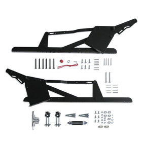
The E900 Hardware for one piece garage doors can be installed in a few hours with common household tools:
- Measuring tape
- Hammer
- Power drill
- Drill bit for lag screw pilot holes
- Impact wrench
- Drive socket to fit lag screws
- Slotted screwdriver
- Locking type pliers
- Prop stick
- Power saw (if final trim of door is done on site)
STEP 1
Measure the overhead clearance in your garage by measuring the distance above the bottom of the header that is free from obstructions (rafters, pipes, garage door opener, etc.) a distance "D" behind the back of the header.
Dimension H = headroom
Dimension D = distance from top edge of door and backside
of header when door is in horizontal position

STEP 2
Select the appropriate headroom hole from Table 1 based on your measurement from Step 1.Dimensions in Table 1 correspond to the typical installation in which the back of the jamb, where the master plate mounts, is approximately flush to the back of the door, where the door angle mounts.

Hardware is pre-assembled in the #1 hole, ready for installation. Change to #2 or #3 holes only when overhead clearance is not sufficient.
For other configurations contact a professional door installer.
STEP 3
Measure door thickness from face of door to mounting surface of door angle and cut-off template accordingly as shown.
STEP 4
Note: it is not recommended that a replacement set of hardware be installed in the existing jamb holes unless at least one of the following is done:Plug the existing holes with dowels. Use through bolts instead of lag screws. Add a support from the jamb to the master plate. Replace the existing jamb (recommended).
Nail rubber bumbers to bottom of header approximately 10" from each jamb. Place top of template even with bottom of header and mark holes labeled "A." Drill 1/4" holes for 3/8" lag screws. Measure 54" from "A" to "Z." Drill 1/4" hole for 3/8" lag screws. Repeat on opposite jamb.

STEP 5
Loosen 3/8" carriage bolts on cantilever arms.Position door in place. Shim 3/8" beneath the door. Door should be 3/8" narrower than the opening on each side. Make sure door is vertically upright with the top of the door against the header.
Mount the master plate to jamb using 3/8" washer and lag screw with its front face flush with jamb face.
Put door angle against door, with the edge of door angle approximately 1/2" from the edge of door, and bolt to door with 5/16" lag screws. (For metal doors, bolt door angle to door with 5/16" x 3/4" hex head machines bolts and nuts.)
After making sure the door is still in the correct position, tighten 3/8" carriage bolts on cantilever arms.
Put door stop in place between door and jamb and mark extension of door stop past jamb edge. When door in raised position, fasten with 1 3/4" long drive nails to jamb face about 6" above the floor. Repeat on opposite jamb.

STEP 6
Put 3/8" x 3 3/4" lag screw in spring angle bracket and screw bolt into hole marked "Z" in Step 4.Move top 5/16" nuts up 2" on each lag of U bolt before installing.
Repeat instruction on opposite jamb.
If the existing installation has a chain for attaching the spring to the jamb, replace the chain with the spring anchor assembly.

STEP 7

STEP 8
Select the correct instruction set (A or B) for the spring combination provided with your hardware.STEP 8A - FOR USE WITH HOOK-END SPRINGS

Single Hook-End Spring
Install spring hook through the U bolt. Stretch spring up and hook over lower bushing on kicker as shown. If hooks are not in line, twist spring in the direction it turns easiest.
Attach Spanner with bolt and nut on each end (see drawing).
Repeat on opposite jamb.
Install spring hook through the U bolt. Stretch spring up and hook over lower bushing on kicker as shown. If hooks are not in line, twist spring in the direction it turns easiest.
Attach Spanner with bolt and nut on each end (see drawing).
Repeat on opposite jamb.
jjjjjjjjjjjjjjjjjjjjjjjjjjjjjjjjjjjjjjjjjjjjjjjjjjjjjjjjjjjjjjjjjjjjjjjjjjjjjjjjjjjjjjjjjjjjjjjjjjjjjjjjjjjjjjjjjjjjjjjjjjjjjjjjjjjjjjjjjjjjjjjjjjjjjjjjjjjjjjjjjjjjjjjjjjjjjjjjjjjjjjjjjjjjjjjjjjjjjjjjjjjjjjjjjjjjjjjjjjjjjjjjjjjjjjjjjjjjjjjjjjjjjjjjjjjjjjjjjjjjjjjjjjjjjjjjjjjjjjjjjjjjjjjjjjjjjjjjjjjjjjjjjjjjjjjjjjjjjjjjjjjjjjjjjjjjjjjjjjjjjjjjjjjjjjjjjjjjjjjjjjjjjjjjjjjjjjjjjjjjjjjjjjjjjjjjjjjjjjjjjjjjjjjjjjjjjjjjjjjjjjjjjjjjjjjjjjjjjjjjjjjjjjjjjjjjjjjjjjjjjjjjjjjjjjjjjjjjjjjjjjjjjjjjjjjjjjjjjjjjjjjjjjjjjjjjjjjjjjjjjjjjjjjjjjjjjjjjjjjjjjjjjjjjjjjjjjjjjjjjjjjjjjjjjjjjjjjjjjjjjjjjjjjjjjjjjjjjjjjjjjjjjjjjjjjjjjjjjjjjjjjjjjjjjjjjjjjjjjjjjjjjjjjjjjjjjjjjjjjjjjjjjjjjjjjjjjjjjjjjjjjjjjjjjjjjjjjjjjjjjjjjjjjjjjjjjjjjjjjjjjjjjjjjjjjjjjjjjjjjjjjjjjjjjjjjjjjjjjjjjjjjjjjjjjjjjjjjjjjjjjjjjjjjjjjjjjjjjjjjjjjjjjjjjjjjjjjjjjjjjjjjjjjjjjjjjjjjjjjjjjjjjjjjjjjjjjjjjjjjjjjjJJJJJJJJJJJJJJJJJJJJJJJJJJJJJJJJJJJJJJJJJJJJJJJJJJJJJJJJJJJJjjjjjjjjjjjjjjjjjjjjjjjjjjjjjjjjjjjjjjjjjjjjjjjjjjjjjjjjjjjjjjjjjjjjjjjjjjjjjjjjjj
Double Hook-End Springs

Install two springs by their hooks through the

Install two springs by their hooks through the
U bolt. Stretch springs up and hook over lower bushing on kicker as shown. If required, twist springs in the direction they turn easiest to line up hooks.
Insert 1/4" x 5/8" bolt and nut for safety lock as shown.
Repeat on opposite jamb.
Insert 1/4" x 5/8" bolt and nut for safety lock as shown.
Repeat on opposite jamb.
jjjjjjjjjjjjjjjjjjjjjKKKKKKKKKKKKKKKKKKKKKKKKKKKKKKKKKKKKKKKKKKKKKKKKKKKKKKKKKKKKKKKKKKKKKKKKKKKKKKKKKKKKKKKKKKKKKjjjjjjjjjjjjjjjjjjjjjjjjjjjjjjjjjjjjjjjjjjjjjjjjjjjjjjjjjjjjjjjjjjjjjjjjjjjjjjjjjjjjjjjjjjjjjjjjjjjjjjjjj
STEP 8B - FOR USE WITH SINGLE CLIP OR PLUG-END SPRINGS


Single Clip or Plug-End Spring
Install "C" hook through the U bolt. Install other hook over the lower bushing in kicker, as shown.
Attach spring to lower hook.
Install "C" hook through the U bolt. Install other hook over the lower bushing in kicker, as shown.
Attach spring to lower hook.
Apply the plate and keeper ring according to sketch & instructions, then stretch to connect to upper hook. Apply plate and keeper ring.
Repeat on opposite jamb.
Repeat on opposite jamb.
JJJJJJJJJJJJJJJJJJJJJJJJJJJJJJJJJJJJJJJJJJJJJJJJJJJJJJJJJJJJJJJJJJJJJJJJJJJJJJJJJJkkkkkkkkkkkkkkkkkkkJJJJJJJJJJJJJJJJJJJJJJJJJJJJJJJJJJJJJJJJJJJJJJJJJJJJJ
Double Clip or Plug-End Springs
Install "W" hook through the U bolt. Install other hook over the lower bushing in kicker, as shown.
Attach two springs to lower hook and add plate and keeper ring, as shown.
Stretch springs to connect to upper hook. Add plate and keeper ring.
Repeat on opposite jamb.

Install "W" hook through the U bolt. Install other hook over the lower bushing in kicker, as shown.
Attach two springs to lower hook and add plate and keeper ring, as shown.
Stretch springs to connect to upper hook. Add plate and keeper ring.
Repeat on opposite jamb.
SPRINGS SHOULD BE STRETCHED ENOUGH TO HOLD THE DOOR UP AGAINST THE HEADER IN THE OPEN POSITION, BUT THE AMOUNT OF STRETCH SHOULD NOT EXCEED 2" AT ANY TIME.
If a spring produces excessive noise when door closes, (a) brace door open (b) unhook spring at kicker and (c) twist the end of the spring 180 degrees IN THE DIRECTION IT TURNS MOST EASILY. Hook Spring on kicker and put bolt and nut in place.
STEP 8C - FOR SPRING ANCHOR

A certain amount of pre-stretch of the springs is required to keep the door snug against the header when open. At no time should there be more than 2" of pre-stretch.
There are two different methods to do this with the same basic hardware:
- Using a heavy screwdriver as shown, force down the lever plate. Raise or lower the upper nuts, with screwdriver still in place as required.
- Raise or lower the upper nuts with a wrench.
STEP 9
Attach screw eye on the inside center of door approximately 20" from the bottom of door. Insert rope in screw eye and tassel and knot both ends.Install handle on the outside center of the door with #10-1 1/2" Drive Screws, approximately 18" from the floor. (For metal doors, fasten door handle with #10 x 1 1/2" flat head bolts and nuts.)
To install slide bolt, put edge of bolt in an open position even with the edge of door, approximately 24" from the floor. Mark the center of the square holes and drill 1/4" holes through the door. Install slide bolt to front of door with 1/4 x 4" Carriage Bolts. Use 1/4" washer and nut on inside of door. (For metal doors, fasten the slide bolt with 1/4 x 1 1/2" carriage bolts and nuts.)

STEP 10 (FINAL ADJUSTMENT, IF NECESSARY)
ADJUSTA-MATIC KICKER
If door is hard to pull down, remove extra shoulder bolt from master plate and insert in the first empty hole above bolt already in kicker. If door comes down too easily, remove extra shoulder bolt from master plate and insert in the first empty hole below the bolt already in kicker.
- Insert bolt as far as possible.
- Apply nut.
- Pull bolt through by tightening the nut with a wrench until fully inserted.
- Put nut on newly inserted bolt.
- Remove nut from original bolt.
- Remove original bolt.
- Repeat on opposite jamb.
Not only have you quickly changed the leverage hole, you have changed the amount the spring will stretch when the door is in the closed position.

CAUTION! ALWAYS MAKE ADJUSTMENT WHEN DOOR IS OPEN. MAKE SURE PROP IS SECURE. (AS IN STEP 7) REPEAT IF NECESSARY.

STEP 11
- By spring adjustment shown in Step 10, door should work easily for 3/4 travel.
- To make door work easily for 1/4 travel, adjust kicker assembly as shown in the circled diagram. ADJUST ONLY WHEN DOOR IS IN OPEN POSITION.
STEP 12 (FINAL ADJUSTMENT)
When the door is in the open position, check to make sure that the door is centered between the jambs. The gap between the left edge of the door and the left jamb should be approximately the same as the gap between the right edge of the door and the right jamb. If the door is not centered between the jambs, follow these steps:- Determine which side has the smaller gap between the door and jamb. This is the side that will be adjusted.
- Securely prop the door open as shown in Step 7.
- Loosen the top lag screw by turning it one full turn counter-clockwise.
- Rotate the top of the master plate toward the center of the door after tapping it with a large rubber mallet until the gap is equalized with the opposite edge of the door. Once equalized, re-tighten the top lag screw. Be sure not to move the master plate.
- Verify that the door is centered between the jambs.
Repeat on opposite door edge.
CHECK AND TIGHTEN ALL NUTS AND BOLTS UPON COMPLETION.


